Calcium Reactors… In, Out and Everything in Between ©
By: Jose Dieck
HIGHLIGHTS:
Although there has been some excellent articles covering calcium reactors; given the number and type of questions I receive it seems that some areas that interest aquarists have not been covered in depth so, at the risk of failing miserably it is my intention with this document to cover specific topics related to calcium reactors a little more in depth than in the past; things like:
Description: What is a calcium reactor?
Economics and suitability: When is a reactor justified?
Related equipment, consumables and design characteristics: What is needed for it to work? How each peripheral equipment and reactor media works and its function? What equipment safety precautions should be followed?
Optional accessories: Things that may make your life easier.
Set up: How to set up the reactor and its peripherals?
Operation: Operating and adjusting the reactor to match consumption.
Maintenance: Refilling, cleaning and maintenance of the reactor’s key components.
And finally I will include some troubleshooting advice.
Now, let’s get started.
WHAT IS A CALCIUM REACTOR? Introduction to the “relatively” easy stuff…
First I shall mention that no matter how it sounds, it is not a dietary supplement to keep your bones healthy…
Now seriously, a calcium reactor is one more automated alternative to continuously replenish the calcium and carbonate alkalinity that is constantly consumed by the critters in our marine and reef aquariums.
Critters like coralline algae, large polyp corals, clams and corals like small polyp scleractinians (Wow! I should have said stony corals) require calcium and carbonate ions (alkalinity) to build their skeletons by deposition of calcium carbonate so they consume these two ions continuously. Means for their replenishment shall be provided for the sake of the critters health and growth.
In generic terms a reactor works by mixing carbon dioxide with the aquarium water to lower its PH and uses this acidic water to dissolve calcium carbonate media into calcium and carbonate ions before returning this “enriched” water back to the aquarium.
It is important to notice that the name “calcium reactor” may give the impression that adding calcium is its main function but as I mentioned earlier it also adds alkalinity and it does it in a “balanced” way which means to add an amount of calcium and an amount of alkalinity in the same proportion that they are consumed by the corals. This ratio is approximately 20 ppm of Calcium for every meq/lt (2.8 dKh) of alkalinity.
In general, because it is easier and more accurate to measure alkalinity with the available kits for the hobby, I would be referring to measuring alkalinity when adjusting the reactor.
ECONOMICS: When is a calcium reactor justified? Or how to insure I get that toy…
As with most alternatives, calcium reactors have some pros and cons when compared with other automated forms of supplementation:
a) The investment 1.5 to 2 times higher than say an automated two part dosing.
b) Its operating cost is lower than DIY two parts when dosing higher volume systems and/or systems with high calcium and alkalinity consumption. This lower operating cost helps pay over time for the difference in initial cost.
c) A calcium reactor operation requires more initial learning and skill but once understood and with proper set up the system is almost set and forget for several months.
d) A Calcium Reactor has less chance of promoting carbonate precipitation in the aquarium pumps and heaters than a high PH DIY or limewater-based supplementation.
e) Aquariums without proper aeration tend to run at a PH that is lower by about 0.05 to 0.1 PH units. In severe cases of reactor undersize, it may be required to supplement limewater to compensate for the PH drop.
f) It can be set up for continued addition via a controller or intermittently by using a timer rather than a controller.
g) Require the use of a high pressure CO2 cylinder that requires the observation of some rules for safe handling.
h) It makes easier to maintain balanced calcium and alkalinity levels as the addition is balanced by design.
i) In systems with high nutrients, it may exacerbate the problem with nuisance algae by providing carbon dioxide although it can also help the growth of macro algae in a refugium.
j) Although some non-commercial media may add contaminants like phosphates, it is the most contaminant free addition compared to DIY or Limewater (Kalk) addition.
k) Does not affect salinity level or the water ionic balance.
l) The supplementation amount is not limited by the amount of evaporation like when using limewater.
Based on cost alone and personal preferences aside, the chart below is a general comparison of cost versus alkalinity consumption for different methods of supplementation for a 120 gal capacity system.
The initial (Fixed cost at zero alkalinity consumption) reflects the average initial cost of the system assuming a 5-year payback.
Note
that, given the wide spread of options and sources for equipment and material
costs the intersection of cost between two different systems can vary
significantly.
 |
Also notice that in general, limewater addition is the cheapest method but will require a second method of supplementation if the consumption is higher than what can be added by limewater alone (Dotted Line shows the points above which limewater alone may not meet the requirements).
A chart for a 55 gal system will show that it will be difficult to cost justify the use of a calcium reactor for small systems. Considering the variability in sources and cost, it might be difficult to cost justify a reactor for systems with a volume lower than between 55 to 75 gallons capacity.
At about 120 gal, (see the chart) a calcium reactor may or may not be cheaper than DIY as it will much depend on the level of alkalinity consumption but as seen on the chart, a consumption higher than around 2 dKh/day may justify the use of a calcium reactor.
For a large system of 225 gal or more a similar comparison shows that a calcium reactor will be the best option cost wise.
RELATED EQUIPMENT or… how the parts make the whole.
The reactor system consists basically of the reactor itself, a source of carbon dioxide (further referred to as CO2), which usually consists of a pressurized cylinder, a regulator, a solenoid valve and a gas adjusting needle valve. Also required will be means to supply aquarium water to the reactor, calcium carbonate media, tubing suitable to handle CO2 as well as tubing or hoses for aquarium water.
Let’s review each …
The Reactor: The calcium reactor consists of a chamber; usually cylindrical, that contains the media, a pump that is used for re-circulating water trough the media, a small valve to adjust the effluent or amount of water passed trough the reactor and in some cases a bubble counter which gives a visual indication of the gas being fed. Some times the bubble counter is located at the gas regulator instead.
Water and CO2 is fed to the recirculation pump inlet, which mixes it and feeds it to the chamber together with water withdrawn from the chamber itself and pumped (re-circulated) back into the chamber. The water leaves the reactor trough a small hose and this effluent water, adjusted by a small valve (the effluent valve) is returned to the aquarium.
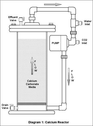 Diagram 1 shows the schematics for a calcium reactor. In this design the effluent flow leaves the
chamber trough the top and the water inlet as well as the CO2 injection is at
the suction of the recirculation pump.
Diagram 1 shows the schematics for a calcium reactor. In this design the effluent flow leaves the
chamber trough the top and the water inlet as well as the CO2 injection is at
the suction of the recirculation pump.
In this design the water flow trough the media is upwards or from the bottom up but as they say “different strokes for different folks” there is a quite variety of designs, all based in the same principle of passing acidic water trough the media.
Let’s review some of the key design characteristics that can make a difference (or may be not…) between one design and the other so you may consider them when evaluating a reactor for purchase.
Chamber Size: The larger and the diameter of the chamber and the taller the media column the more media capacity there is so the higher the reactor capacity and/or the longer the time between media top offs will be. Well… that one was easy right?
Virtual height of the media column: What? Well let me explain. Every time the water passes trough the media it is equivalent to having a media column equal to its height. If the water re-circulates five times, it will be equivalent to have a media column five times taller in comparison to a reactor with no re-circulation pump thus achieving a virtual height of five times. A more powerful pump may re-circulate say ten times thus creating a virtual height twice as tall as the reactor with the pump re-circulating only five times.
The higher the virtual height of the media the longer the time the media will be in contact with the acidic water or in other words the longer the retention time will be and the longer the time, the more effective the dissolution and CO2 consumption will be.
Also the higher the virtual height, the higher the water velocity will be thus making it more effective to drive the calcium and carbonate ions away from the media surface resulting in an increased performance.
In summary, a larger re-circulation pump will increase the performance by increasing the virtual height of the media thus the increase in retention time and the flow velocity.
Now hold your horse! This does not mean that installing a swimming pool size pump in a reactor will make it better, of course there are practical and physical limitations to the size of the pump, limitations like wasted power consumption, propensity for cavitation at the pump, vibration, media tumbling and breaking apart, media carry over and so on.
Direction of flow: In an effort to improve the water flow trough the media and prevent channeling, there are reactors designed so the water can flow trough the media either upward, downward and some even give the option for radial flow from the center of the chamber toward the outside walls by using an optional spray bar installed vertically at the center of the chamber and surrounded by the media.
Each has advantages and disadvantages. Comparing the two most popular, up-flow versus down flow:
Up-flow, which is becoming more popular, has the advantage of keeping a cleaner space between the media grains. As the media dissolves, fine particles remain which form a mud that may plug the interstitial space between the grains thus promoting channeling. With an upward flow those particles are carried toward the top of the media were they can exit the reactor with the effluent flow.
Note that a good portion of the particles will flow trough the recirculation loop before getting out. This helps to dissolve them further but also an excess of particles, especially larger ones carried over will reduce the life of the pump impeller.
This damaging effect was very noticeable in reactors designed to fluidize sand like sized media. These reactors were very efficient in dissolving the media and could achieve unusual high calcium and alkalinity concentration in the effluent but that extra capacity was obtained in exchange of a shorter recirculation pump life. In the newer design of fluidized reactors, that effect was avoided by the addition of a foam filter to the top of the chamber in order to capture the fine particles.
The second potential issue is that particles leaving with the effluent may have a tendency to plug the effluent valve if it is installed at the outlet, especially when using a needle effluent valve.
Furthermore, these particles; which lack the magnesium coating that prevents precipitation will, upon returning to the aquarium have a tendency to promote precipitation upon their surface of calcium and carbonate ions thus removing part of the ions we are trying to supplement. How much this effect reduces the effectiveness of the addition is really unknown but in my opinion it might be negligible although if the particles are deposited on the sand bed, they can promote clumping.
Finally, if the effluent outlet is not located directly on the top of the chamber, an up flow reactor may have a tendency to accumulate bubbles (Air or CO2) at the top of the chamber. When this accumulation is excessive, the pump may loose priming, the recirculation may stop and running dry may damage the pump. By the way, as a general rule, unless the reactor has a gas chamber at the top purposely designed to re-circulate the accumulated gas; it is my preference that the effluent outlet be located at the top of the chamber regardless of the flow direction.
A downward flow reactor will have a tendency to accumulate the muddy particles at the bottom of the media bed were a foam filter is placed. The filter protects the pump impeller and prevents the particles from re-circulating and leaving the reactor but eventually this mud plugs the filter and part of the media bed thus creating a pressure drop that promotes channeling and reduces the total flow trough the media.
This effect can be significantly reduced by using large sized media grains and by cleaning the filter and rinsing the media every four to six months.
Construction: Most reactors are made out of acrylic and PVC piping. It is important to insure that the acrylic is of the proper thickness. Flanges of less than 1/4" may bend when tightened, too thin of a chamber cylinder walls can’t make for strong joints between the cylinder and the flanges or piping.
My preference is for reactors with a flange at the top in a way that when removed, it allows for full access to the inside of the chamber making maintenance and cleaning a lot easier.
It is also preferred that the cover flange has keyholes for the holding screws so the screws do not have to be totally removed when opening the chamber. Nylon screws with thumb heads for removal make it also very convenient so no screwdriver is required.
It is preferred that the edges of the flanges are not sharp but rounded and hand polished or machined but not flame polished as this last method may promote crazing which may develop into small cracks.
The pump should be firmly attached to either the base of the reactor or the top flange. If supported by the recirculation piping, the piping and the points were it attaches to the chamber or to the flanges should be strong enough to support the weight and vibration.
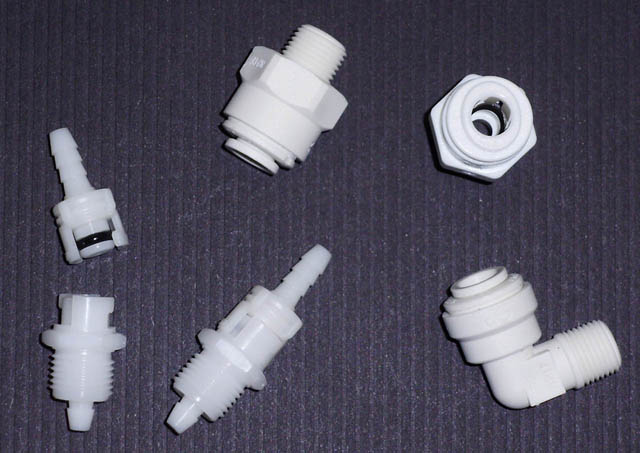
Another convenience is the use of quick John Guest type connectors for easy connection of the feeding and effluent tubing.
 |
Keep in mind that a needle valve is used to adjust flow and not as an on
off valve, closing a needle valve too tightly will leave indentations in the
needle which will make difficult to get proper flow adjustment afterwards.
Finally take a good look at the seals; specially take a look at the groves and “O” rings sealing the flanges and unions.
The “O” ring should seat at the bottom of the grove deep enough that only a slightly more than half its thickness fits inside the grove while at the same time it fits snuggly against the grove walls, this way when the “O” ring is compressed, it will seal also against the sides of the grove and not only at the top and bottom.
Are you still with me? I hope I did not lose you yet so let’s talk about the next component.
Source of carbon dioxide: The carbon dioxide is a nonflammable, colorless, odorless, slightly acid gas that is approximately one and a half times as heavy as the air and as such, when it leaks will have a tendency to accumulate in lower areas.
CO2 is shipped and stored in DOT (US Department of Transportation) approved high-pressure steel or aluminum cylinders having a minimum service of 12,410 kPa (1,800 psi) as a liquid under its own vapor pressure of approximately 5,727 kPa (830 psig) at 21.1 oC (70 oF). As a side note, at about 31 oC (87.9 oF) all liquid inside the cylinder will turn into gas and the cylinder pressure will be at about 7,390 kPa (1,071 psi).
Carbon Dioxide has many uses. A substantial volume of CO2 is used for carbonation; yes, the fizz and bubbles in your soda pop is carbon dioxide.
As a liquid or solid in the form of “dry ice” is also used for refrigeration and freezing, it is also used in fire extinguishers, in canned food products and also used in PH control, which is the application, we are mostly interested in.
When carbon dioxide is mixed with water, it will form the weak acid, carbonic acid. This acid is what allows us to lower the PH of the aquarium water and to dissolve the calcium carbonate media.
Carbon dioxide can be supplied in different purities from the commercial grade that is 99.5% pure up to a research grade that is 99.995% pure and I should add extremely expensive.
For our application, commercial grade that is mostly used as a shielding gas for welding is good enough although grades used for beverage or the one used for medical or anaerobic applications could be even better but not readily available.
I would recommend you getting the CO2 and the cylinder from a reputable welding store to insure the purity of the product and the safety and maintenance of the cylinder. Try to stay away from CO2 used for paint ball guns as it is often contaminated with oil or hydrocarbons.
Most welding distributors will be able to handle standard size cylinders in exchange especially if you acquired the cylinder from them. You may not get your beautiful new original cylinder back but exchanging will insure that the cylinder you are getting has always been inspected tested and the valve properly maintained at no additional cost.
At this point it is important to talk about some CO2 safety rules (Insert your favorite disclaimer here)
1. Do not place the cylinder were it might become in contact with an electric arc. Arc burns can weaken the cylinder walls not only permanently damaging the cylinder but also creating a potential for a catastrophic failure.
2. Do not store the cylinder in an enclosed area and insure proper ventilation.
3. Always tie or support the cylinder so it does not fall, if it falls and the valve breaks at the neck, the cylinder may take off like a rocket.
4. Do not discharge CO2 in confined spaces. As it displaces the air it can cause asphyxia.
5. Before using, read all information and precautions on the cylinder labels.
6. Although cylinders of 20 pounds capacity or less are permitted to be used or transported without the valve protection cap, it is always preferably to have one installed when moving the cylinder. Larger than 20 pound capacity cylinders should always be moved with the protection cap installed and it shall not be removed until the cylinder has been properly secured to prevent it from falling.
7. The only safety device permitted in CO2 cylinders is a bursting disk installed in the valve that will break if the pressure reaches the point were the cylinder may burst open. Never tamper with this safety device. Once it ruptures it will not be possible to prevent releasing the full content of the cylinder.
8. Protect the cylinder from direct exposure to the sun and high sources of heat and never leave it in the vehicle for long period of time. When taking the cylinder to be refilled, make it the last chore of your list so after filling, you return directly home.
9. During filling, the cylinder gets very cold. Avoid receiving a cylinder that is still cold. As the cylinder warms up, the liquid inside expands and if overfilled it may create excessively high pressure thus, newly filled cylinders must always let to warm up to ambient temperature before transporting.
10. CO2 cylinders are filled by weight and on a scale. Be aware from places that will just transfer filling without weight, as it is easy to overfill a small cylinder. Do not get annoyed is a supplier refuses to fill a particularly small cylinder as most likely will not have the required small scales required to do it safely.
11. Close the cylinder valve when the cylinder is almost empty leaving some positive pressure in the cylinder to prevent it from contaminating with air.
12. Always use a check valve between the regulator and the reactor to prevent water from back siphoning into the regulator or the cylinder.
13. Never use the CO2 cylinder without a suitable regulator to control the delivery pressure.
14. Always test for leaks when connecting the system to the reactor. CO2 leaks can be detected by painting the connections or suspected areas with a solution made by mixing some dishwashing soap with water.
 Now that you have memorized these 14 safety rules, did you? Yes? Then I
can continue…
Now that you have memorized these 14 safety rules, did you? Yes? Then I
can continue…
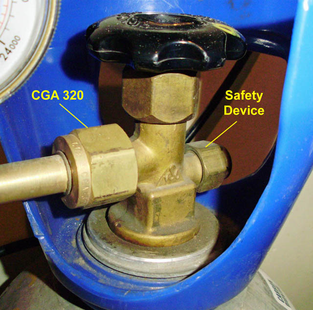
The valve used in the cylinder is typically made out of forged brass and in the US has a Compressed Gas Association (CGA) connection type 320 (Diagram 2) that require a flat washer to provide the seal. This washer shall be replaced every time the regulator is reconnected.
Do
not use Teflon tape or any other sealant but the washer. The company filling the cylinder shall be
able to provide you with the new washers.
 |
The CO2 cylinders come in different capacities. For a typical reactor application a 10 pounds capacity cylinder feeding at 40 to 50 bubbles per minute will last 8 to 12 months.
Given the difficulty finding facilities to fill smaller cylinders I would recommend a minimum of 10 pounds capacity be used. Also given the weight of the cylinder, I would recommend for easier handling to use a cylinder made out of aluminum.
The Gas Pressure Regulator: The Gas pressure regulator, that thingy that looks like a Mickey Mouse is a device that is connected to the CO2 cylinder and has the function to lower the high pressure CO2 gas to the pressure required for the reactor to function.
The
regulator not only reduces the pressure but also acts like a dynamic valve to
maintain a constant pressure level at the delivery outlet regardless of the
changes in flow, which is something a manual valve cannot do.
A regulator specified for CO2 use is built of CO2 compatible materials as well as being fitted with the right CGA 320 connection type (For US). Never use a regulator specified for a different gas.
Most
regulators have two pressure gauges; the one closer to the connector to the
cylinder measures the pressure of the CO2 in the cylinder while the other is
used to measure the delivery pressure. They also have means to adjust the
delivery pressure set point, typically using a pressure adjusting knob in the center of
the regulator body (See Diagram 3).
Internally
the regulator is fitted with a diaphragm, a range spring and the poppet assembly. This assembly which acts like a dynamic valve, is
a conical piece on a stem that is connected to the diaphragm.
 The operation is rather simple; as the gas gets consumed, the pressure
in the delivery chamber tends to drop reducing the upward force upon the
diaphragm, which then tends to drop. As it tends to drop the poppet assembly
lowers increasing the opening in between chambers thus letting additional gas pass
from the inlet high-pressure chamber into the delivery lower pressure chamber.
The operation is rather simple; as the gas gets consumed, the pressure
in the delivery chamber tends to drop reducing the upward force upon the
diaphragm, which then tends to drop. As it tends to drop the poppet assembly
lowers increasing the opening in between chambers thus letting additional gas pass
from the inlet high-pressure chamber into the delivery lower pressure chamber.
As gas passes from the high pressure chamber into the delivery chamber, the pressure in the delivery chamber is restored, the force upon the diaphragm increases so it pushes it upwards thus pulling up the poppet which then reduces the size of the opening in between chambers partially closing it.
The range spring provides the force upon the diaphragm that forces it down to open the poppet so, the stronger or more compressed the spring is the more pressure will be required inside the delivery chamber to rise the diaphragm and as a result the higher the delivery pressure will be.
In other words, to increase the delivery pressure, the pressure-adjusting knob is turned in (Clockwise) to compress the spring.
Replacing the spring with one with higher or lower strength can change the delivery pressure range of the regulator.
Now that we understand a little better how the regulator works, I am able to explain a bit more about some of the odd behavior of some regulators and why some may behave differently than others.
Assume for a moment that the diaphragm is not very flexible. Under this scenario the force required to flex the diaphragm will be bigger; equivalent to having a stronger or more compressed spring so, the delivery pressure must be higher in the delivery chamber for the regulator to properly operate. As a result, a regulator with a less flexible diaphragm, say a metallic diaphragm rather than rubber (usually Neoprene) will be stronger and last longer but will not be able to deliver a low enough pressure.
This is important because the higher the delivery pressure, the more difficult will be to adjust the flow of CO2 because very small adjustments to the CO2 needle valve will result in a large change in flow and some times the needle valve is not sensitive enough thus making bubble rate adjustment almost impossible.
In addition, a less flexible diaphragm will take longer to react to changes in pressure, this delay in reaction time will let more gas pass between chambers before the poppet acts creating more of a closing and opening effect rather than a throttle effect resulting in a delivery pressure that cycles higher and lower as the poppet opens and closes also resulting in a cyclical increase and reduction of the CO2 flow rate.
A smaller diameter diaphragm will pretty much behave as a less flexible diaphragm causing similar effects.
In summary a regulator with a larger diameter diaphragm of a more flexible material with a lower strength spring will be more sensitive, accurate and provide a more stable delivery pressure, unfortunately it will be prone to more frequent failure and rupture of the diaphragm thus the manufacturers usually compromise and design for longevity and economy resulting in too high a delivery pressure making many regulators available in the hobby only marginally suitable.
The number one complain I hear and the number one reason why calcium reactors have developed certain reputation for being difficult to set up and to need a lot of tinkering, is the difficulty in adjusting for a low and stable enough CO2 bubble rate which is mostly due to the limited capability of the regulators available for the hobby.
There is one hobby regulator out there with a larger diaphragm made out of Neoprene that is sold for planted aquariums, unfortunately it seems to have been discontinued and replaced with an electronic version using technology that has a good potential of having solved the issue of bubble rate stability but in my opinion is still a bit too new to have proven its sturdiness and reliability.
A definite albeit expensive solution comes in the form of a two-stage regulator. This type of regulator contains two regulators (stages) in a single body. While a single stage hobby regulator has a minimum delivery stable pressure in the order of 20 to 25 psi a two-stage regulator can reliably achieve delivery pressures in the order of 3 to 5 psi. Because the first stage reduces the CO2 cylinder pressure from around 830 psi to 90 psi, the second stage has to deal with a reduction from only 90 psi so it is able to deliver reliably a delivery pressure that can be 5 to 7 times lower than a typical single stage hobby regulator.
Unfortunately, this type of regulator is not readily available for the hobby, does not include the needle and solenoid valves as the hobby ones do, it is twice as expensive and is somehow bulky and heavy.
 |
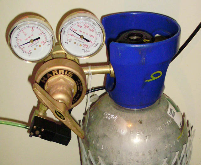
For
several months now I have been using a two-stage regulator manufactured for
low-pressure industrial applications by Harris (See Picture 3: Part No. 3302276
Model 9200-15-320 with delivery range 0 to 15 psi).
I am really pleased with it because this regulator has been able to maintain reliably a constant pressure of 5 psi without surging. It is so precise that I do not need to adjust the needle valve to change the bubble rate which instead can be adjusted by using the pressure adjusting knob instead, the bubble rate is so stable that I have been able to maintain a constant PH level in the reactor without the need of a controller and without the need to make any adjustment for a couple of months!
On the other hand, if you go for it; and I guess you are already temped… be prepared to spend in a solenoid and a needle valve separately in addition to the around $300.00 US for this regulator. Note that you will also need some adapters to connect the solenoid and needle valve to the regulator.
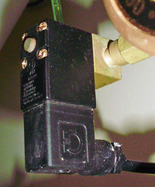 |
When
it is not powered the valve is normally closed so there is no CO2 flow. When
power is applied, the solenoid turns the electricity into a magnetic field that
actuates the stem on the valve to open it.
In general solenoid valves used in the hobby will be very reliable as far as they are designed for continued applied powered in other words, designed for 100% cycle, if it is not, the coil may overheat and fail when continuously powered up.
The most common cause of failure that prevents a solenoid valve to operate properly is having salt-water back flowing into the valve, once the water evaporates salt deposits inside the valve; besides corroding the components, will prevent it from operating properly.
To prevent back flow from happening, a quality check valve should always be used between the regulator and the reactor.
 |
The
more turns you need to fully open the valve, the more precise the valve will
be.
What to look for in a regulator assembly…
Look for a sturdy regulator and with as many bronze components as possible because steel parts usually corrode over time if accidentally splashed with salt water.
Also, look for a regulator with large diaphragm diameter. This is usually indicated by a body of a larger diameter.
Regarding the pressure gauges, the
larger their faceplate is the easier they will be to read and usually the
more accurate they are. Gauges with a two inch diameter faceplate will be my minimum
preferred.
As with the cylinder valve, insure that the fitting for the cylinder matches that required by your region of the world.
There are some regulator models out there that come with a pre-set delivery pressure and without pressure adjusting knob; these were usually preset for around 40 psi which in my opinion makes flow adjustments with the needle valve too sensitive and difficult to achieve but now some new versions come preset at around 15 psi so if you are getting one of this type, just insure you are getting the lower pressure version. Regardless, my preference is still for being able to adjust the pressure.
 |
Most hobby regulators come already with integrated solenoid valve and needle valve and some also include the bubble counter although if your reactor is fitted with a counter one of the counters may become redundant. Although using both is not an issue, always use only one and the same to make the adjustments.
Also do not forget to look for a regulator fitted with a good quality and precision needle valve; it will make your job easier in the long run.
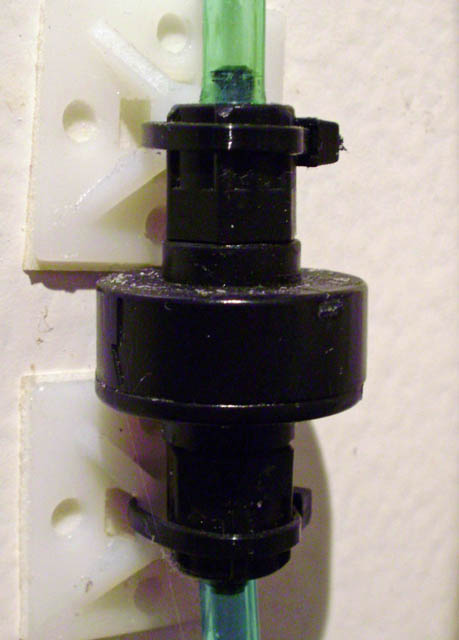
Finally as mentioned before, a good CO2 check valve is also required to prevent water from the reactor to flow back into the regulator trough the CO2 line.
Because the regulator, solenoid and needle valve are subject to the same high pressure the cylinder is, certain precautions are also required:
1. Keep the regulator clean, check the connections and the cylinder valve for dirt and clean it before making the connection.
2. Never use a regulator that has been dropped or one that is designed for a different gas and never swap inlet fittings. Each CGA fitting is designed for a particular gas use to insure that the wrong gas cannot be connected to the wrong regulator or point of use.
3. Never replace the delivery pressure gauge with one of a lower range. It can blow if the pressure-adjusting knob is fully screwed in.
4. Do not use pipe sealants on the connector to the cylinder nor use any type of lubrication in a regulator.
5. Always close the regulator before connecting it to the cylinder and before opening the cylinder valve. To do so, fully unscrew (Counterclockwise) the pressure-adjusting knob until it feels a bit loose. This will insure that the poppet is closed thus preventing an instantaneous shockwave of gas into the low-pressure delivery chamber that may rupture the diaphragm or damage the delivery pressure gauge. If by chance you totally remove the knob, just screw it back in a bit.
 |
Now
the regulator is ready for you to use the knob to adjust the delivery pressure.
The right sequence for opening will be. Cylinder valve > adjusting knob > Apply power to solenoid valve > open and adjust needle valve.
6.
Insure that there is no pressure inside the regulator before disconnecting it.
To do so, always close the cylinder valve before closing the regulator or
the needle valve and wait until both gauges indicate that there is no pressure.
The right closing sequence is:
(a) Close the cylinder valve and wait until the gauges indicate that there is no pressure. (b) Close the regulator
using the adjusting knob. (c) Remove the power to the solenoid valve. (d) Close the
needle valve (do not tighten it).
Reactor Accessories: These are what I would term “nice to have” items but not strictly necessary.
Here is a list of some of my favorites:
 |
This
device can make the amount of CO2 easier to control especially if the regulator
or needle valve is not precise enough to maintain a very stable CO2 bubble
rate.
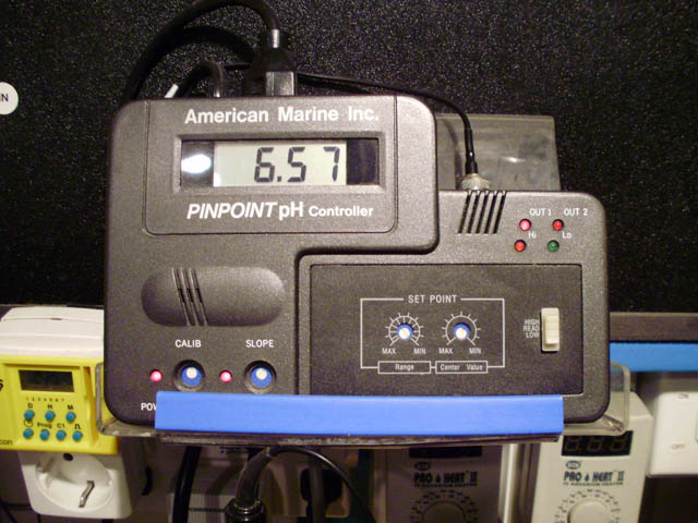
Some considerations regarding PH controllers:
The controller can not only be used to control the CO2 ON or OFF states but if you have a stable CO2 flow, then you can use the controller as a safety measure to only close the CO2 in case that for any reason the PH drops too much. In this case the solenoid is always open and closes only when a too low of a PH is reached.
My preference is for a
controller that can be set for both a low PH as well as for high PH set points
by providing an adjustable span of control (the difference between the high and
low PH set points) so you can adjust the responsiveness.
Also the controller should be capable of being calibrated not only for a single reading point (calibration) but also for a second reading point (the slope) providing for more accuracy throughout the full range of readings.
Follow the manufacturer’s recommendations on how to calibrate, connect and set the controller.
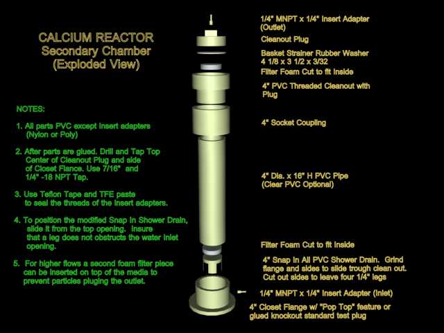
B) Second media chamber: This consists of a second cylinder that is filled also with calcium carbonate media. The effluent leaving the first chamber is passed through the second chamber (usually up-flow) before being returned to the aquarium. This will help improve the calcium and alkalinity saturation by helping to convert more carbonic acid into bicarbonate, and as a result increasing the PH level in the water leaving the reactor helping to reduce the PH lowering effect created by the use of the reactor.
The reactor can be fitted with a second chamber directly from the manufacturer or the second chamber can be purchased separately. If you are a good Do It Yourselfer, you can also build one (See Diagram 4).
 |
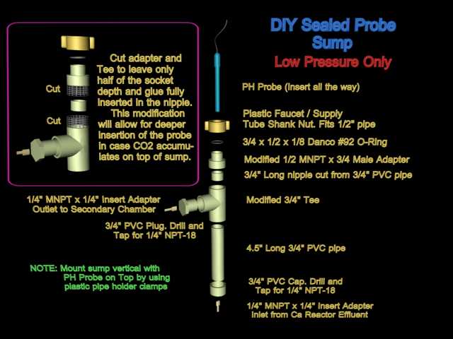
Note that when using a second chamber in combination with a controller, the PH probe of the controller shall be installed in a way to measure the PH of the water in the first chamber or in the recirculation loop. Reading the PH of the final effluent will greatly reduce the controller responsiveness because by the time a change in PH is detected at the effluent, the change of PH in the first chamber could be already way out of range.
If your two chambered reactor do not have means to install the probe in the first chamber or the recirculation loop, you can easily build a probe sump or chamber that you can install between the first chamber and the second chamber of the reactor thus measuring the PH of the effluent from the first chamber (See Diagram 5).
 |
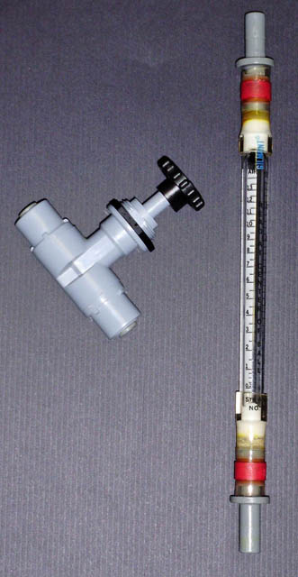 |
C) Flow Meter: The typical means of measuring the effluent flow is to use a stopwatch and a small measuring cup to catch and measure the amount of effluent delivered for one minute. This works pretty well but is a bit cumbersome.
A way of continuously measure the effluent flow is by using a flow meter. A flow meter is a calibrated glass or acrylic tube that has an internal float which rises with the flow. The higher the flow, the higher the float will rise thus providing a continuous visual indication of the amount of flow passing thru.
An excellent flow meter for this purpose is the Gilmont unshielded direct reading glass flow meter with glass float and flow tube size 13 with a range of 2 to 300 ml/min (Around $110.00 retail).
A cheaper alternative could be the Dwyer acrylic meter RMA-33 (10 to 110 ml/min) or the RMA – 34 (20 to 300 ml/min) Unfortunately the short scale of the Dwyer can make it less accurate and more difficult to read but still will provide a good reference.
 |
Note that for CO2, not all tubing is created equal. Some materials become brittle or CO2 can diffuse trough the tubing walls so insure that the tubing used is specified for carbon dioxide use.
There are other accessories like pressure gauges to measure the pressure in the chamber, water pre-filters and CO2 diffusers but in my experience they really do not provide much of an advantage.
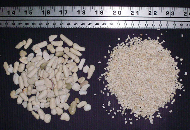
The Calcium Carbonate Reactor Media:
Together with power, CO2, and your alkalinity test kit, calcium carbonate media is the fourth consumable for the reactor.
The media could be either pure chemical calcium carbonate or more typical it is media that is quarried out or collected from old carbonate deposits formed by coral skeletons.
Calcium carbonate can take two different crystal forms. Calcite, which is usually the form in marine shells of clams, oysters, snails etc. and aragonite, which is usually the form in coral skeletons and some algae like halimeda.
Look for aragonite media, as it is easier to dissolve and do not require a very low PH to do so.
 |
Although a lot has been said in the past regarding the purity of reactor media, in my opinion most if not all commercially available media today meets the purity required for aquarium use. As an example, in my tests of two of the most popular medias using a colorimeter, the level of phosphate detected in the effluent was a maximum of 0.02 ppm, which is below the recommended minimum of 0.03 ppm recommended for the aquarium water and it is way below the amount contained in the food you would add when feeding your fish and corals. For this reason, the addition of a phosphate removing reactor after the calcium reactor is not only not necessary but may be even detrimental because the high content of alkalinity and calcium in the effluent will rapidly create calcium carbonate precipitate in the phosphate removing media surfaces.
Finally in order to provide not only calcium and alkalinity but also magnesium, some magnesium carbonate media (dolomite) could be added to the reactor. If you do so, only about 10% of the total media is needed. Note that the magnesium carbonate media is more difficult to dissolve so it will require running the reactor at a lower PH than you otherwise would.
I no longer use dolomite in my reactor because of lowering the PH too far increases the PH lowering effect of the reactor and increases the tendency to turn calcium carbonate media into mud and because it is easy to supplement magnesium by other means.
Other things you will need:
If you will not be using a controller, you will need a PH monitor because a PH chemical test kit or strips are not accurate enough to measure the effluent PH.
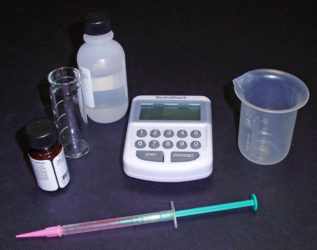 |
You will also need a good alkalinity test kit, a small 100 ml plastic measuring cup and a stopwatch to measure the effluent flow if you will not be using a flow meter.
Depending on the type of bubble counter, a plastic syringe will become handy for filling the bubble counter.
If your bubble counter is installed in the regulator, you can use pure glycerin for the bubble counter; it will make the CO2 bubbles rise more slowly so it will make them easier to count. You can get the glycerin from your nearest pharmacy.
I would not recommend using glycerin in a bubble counter mounted in the reactor as there will be greater chance of it mixing with the aquarium water especially if the bubble counter is designed to be auto filled when the reactor is in operation.
SETTING UP THE SYSTEM or how to finally get
to play with your new toy…
There are three potential means to feed water to a reactor or variations “thereof”: Did you notice this cool word I learned from my associations with Lawyers?
Those feeding methods could be either by Gravity, by using a T-off from the return pump, by using a peristaltic pump or by using a power head to pump water into the reactor.
The use or gravity by just using a hose or tubing to drain water from a higher level into the suction of the recirculation pump can work under the proper circumstances specially when using a rather large recirculation pump. It has the disadvantage that as the media dissolves or starts getting plugged; the change in recirculation pressure ends up in changes to the effluent rate so using gravity may not provide for a really stable effluent flow.
The second alternative, which is connecting the feed line to a T-off the discharge of the return pump, can also work under the right circumstances but with some caveats.
In my early “Dumb Dumb” days I connected my reactor to a T-off from the discharge of my Iwaki 100 RLT return pump pumping water to my tank one floor above. Half an hour later the top of the reactor popped open.
Calcium reactors are not built to really run pressurized. A slight pressure of 2 to 5 psi is about the range they can operate safely. At between 5 to 10 psi most reactors will start leaking and at 10 psi you will be applying a 330 pounds of force to the top flange of a 6.5” dia. reactor chamber so anything above that is running the risk of blowing the top or cracking the reactor cylinder.
Moving the effluent valve to the inlet of the reactor while leaving the output fully open is a way to avoid excessive pressure but in doing so you will find out as I did that the effluent flow is not as stable especially if you feed other devices from the return pump. A bit of debris in the income water or changes in the adjustment of any one of those other devices is enough to change the inlet pressure ending up in changes in the effluent flow.
The use of a peristaltic pump to feed the reactor is the method that provides the best effluent flow stability of them all but good peristaltic pumps are not that cheap. You will require a peristaltic pump that provides continuous flow, is specified for a 100% cycle or able to work 100% of the time without stopping and with a flow capacity that is adjustable between 20 and 150 ml/min.
Finally, the way I found that provides good effluent flow stability for the money is to feed the reactor by using a power head. A MaxiJet 1200 seems to be well suited to do so.
You can connect the reactor inlet line to the discharge of the power head in a couple of different ways.
First it is important to notice that the power head is designed to pump a lot more water than what the reactor will require so the small volume of water will not provide for proper cooling of the power head and the increase in temperature will promote calcium carbonate precipitation in the power head shaft eventually ceasing the pump rotor and getting it stuck.
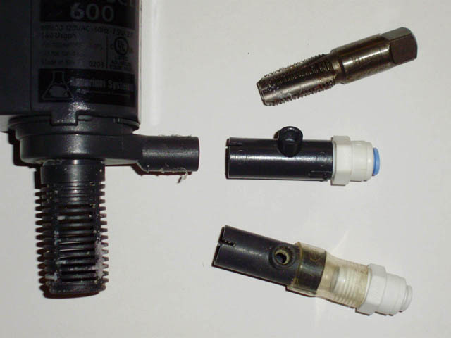 |
Instead of connecting your feed line directly to the power head outlet, connect the line to the coupling that comes with the power head, the one that has a hole originally to be used for the injection of air to the power head, then just insert the coupling to the power head outlet. For further reference, this is the cylindrical coupling that support the fan like piece used to redirect the power head flow. Remove the fan like piece; cut away the two little pins that support the fan like piece and you will have it ready to insert a hose into it.
You can also use a tap to thread the inside of the coupling and install a John Guest connector to attach a ¼” poly line to it. (See Picture 13).
So let’s start with the setup (See Diagram 6).
First, select the location for the installation of the reactor. You should have enough room and headspace for the reactor and the CO2 cylinder so they can be close enough to your water source, usually the sump.
The location should be flat and level and at a height that is at the same or be lower than the level of your water source to facilitate bubbles leaving the reactor and for the feed power head to work less in overcoming head pressure.
Also the location should provide for means to tie and secure the CO2 cylinder in a vertical position.
Finally an electrical outlet will be needed nearby.
 |
If the calcium reactor came disassembled, start by assembling the reactor following the manufacturer instruction manual. Usually this implies installing and connecting the recirculation pump as well as the installation of the effluent valve and the recirculation loop. I would recommend applying silicon grease to all the “O” rings for proper sealing and longer life. Use very little grease; once the “O” ring is lubricated, use a paper towel to remove the lubricant from the “O” ring as all that is needed is for the “O” ring to “shine” a little bit.
Rinse the media in a bucket under running water until the water is milky but not dirty. Fill the reactor chamber with media up to the height indicated by the manufacturer, in most cases this will be three quarters of the chamber full or a bit higher.
Secure the cylinder in place, once secured, if the cylinder came with a valve-protecting cap, unscrew and remove the cap. By DOT regulations, all cylinders larger than 20-pound capacity must be fitted with one when the cylinder is moved or transported.
Remove any shrink seals or plastic caps protecting the valve outlet and connect the regulator to the cylinder. Do not forget to use the washer seal. Use the proper wrench to tighten the connection. Using a pipe wrench or a slip wrench may damage the connector.
If your regulator is fitted with a bubble counter, fill the bubble counter with distilled water or glycerin.
Connect the CO2 tubing to the outlet of the bubble counter or to the needle valve if the regulator is not fitted with a counter.
Regardless of how close the cylinder is to the reactor, use at least three feet of CO2 tubing between the regulator and the reactor as some water may flow back into the tubing when closing the regulator.
If you have an in line check valve, cut the tubing at approximately the mid section and connect both ends of the check valve to the tubing. Insure that you have the right orientation for the check valve and that the flow-indicating arrow is pointing toward the reactor side. Most check valves operate better when mounted vertical.
Connect the end of the CO2 line to the CO2 inlet of the reactor at either, the check valve in the reactor if it comes fitted with it or the bubble counter in the reactor if it comes fitted with one and no check valve. If the reactor comes with neither a check valve nor a bubble counter the CO2 inlet is usually located at the suction of the recirculation pump, check the manufacturer manual for the right location of the CO2 inlet connection.
You do not need to fill the bubble counter in the reactor if the regulator is fitted with one. If not, just fill the reactor’s bubble counter with distilled or RO/DI water, do not use glycerin in the reactor’s bubble counter.
Install the water feed power head in a location were it would not suction any bubbles and connect it with tubing to the water inlet of the reactor at the location indicated by the manufacturer instructions.
Finally connect the effluent line from the effluent valve back to the aquarium, usually back to the sump. Insure that the end of the effluent line is not submerged so if CO2 bubbles leave the reactor, those do not bubble under the surface of the aquarium water.
The best location for dripping the effluent is near the suction of the skimmer pump. This will help to improve aeration of the effluent once mixed with the aquarium water and help minimize the PH reducing effect of the effluent by the skimmer aeration aiding in the conversion of carbonic acid into bicarbonate and bicarbonate into carbonate.
If your reactor is not fitted with a PH probe connection then you will need to measure the effluent PH at the point where the effluent returns to the aquarium.
To do so, you can hang a plastic cup on the inside wall of the sump. Place the effluent line in a way so the effluent drips into the cup and the cup overflows into the sump. You can place the PH probe in the cup so it will be measuring the effluent PH. Note that this method works only with single chambered reactors. If you have a second chamber you will need to measure the PH at the first chamber so you will need a PH probe connection port in the chamber or in the recirculation loop. As described above you can DIY one as per the instructions given.
OPERATING AND ADJUSTING THE REACTOR: Now the really fun part …
In reality it is not difficult to operate and set up a calcium reactor if you get familiar with some basic principles of operation.
Keep in mind the four basic rules of a calcium reactor operation:
1. A calcium reactor adds balanced amounts of calcium and alkalinity. If you start with unbalanced levels, do not expect the reactor to balance the levels back. If the levels start unbalanced, they will remain unbalanced although at a different level.
2. A calcium reactor is not meant to increase or adjust the levels, if you try to do so, chances are you will never be able to adjust the reactor properly and you will keep on overshooting your target.
3. Your reactor system should be able to maintain a continuous and a stable effluent flow and CO2 bubble rate, if it does not, it will be impossible to operate it properly.
4. Be patient, be very patient. The reactor will take several hours to stabilize after any adjustment. Trying to adjust it too often before it has achieved stability will only make things more difficult and frustrating.
The idea behind adjusting the reactor is rather simple. Because it will add calcium and alkalinity in a balanced way, we are only concerned about adjusting the addition of alkalinity to match the aquarium alkalinity consumption and the calcium in most cases will take care of itself.
Reactor controls: There are two main controls for the reactor. The CO2 needle valve used to adjust the amount of CO2 to be added and the effluent valve that is used to adjust the amount of water that passes thru the reactor and is added back to the aquarium.
In general; the more CO2 added, the lower the PH in the reactor will be and the lower the PH in the reactor the higher and faster the dissolution is resulting in more alkalinity in the effluent. The media starts dissolving at a PH of about 7.7. A reactor using aragonite media is usually run at a PH between 6.5 and 6.7.
At a PH below 6.5 the media will have a tendency to crumble turning muddy so for aragonite my recommendation will be to run the reactor at the stated range. Important will be to note that calcite media will require a lower PH as far down to about 6.3.
For the effluent control, the higher the effluent flow for a given PH in the reactor, the more alkalinity will be added to the aquarium. Note that changing the effluent flow rate will have an effect on the PH if the amount of CO2 is not changed. When increasing the effluent flow without adding more CO2, the amount of CO2 in proportion to the effluent will be reduced and as a result the PH in the reactor will increase.
So in summary, changing the CO2 rate (bubble rate) will change the PH and amount of alkalinity in the effluent but will not affect the effluent flow. Changing the effluent flow will change the PH so adjustments to the CO2 rate will be needed if it is desired to maintain the PH level previous to the effluent volume change.
Using these two controls it is possible to adjust the total alkalinity added to the tank so a balance between addition and consumption can be achieved.
There are two different ways to match the reactor’s daily alkalinity supplementation to the daily consumption of alkalinity in the aquarium. Both methods imply trial and error. In other words the reactor is started, the aquarium alkalinity is tested every 24 hours and the reactor is re-adjusted accordingly every 24 hours to increase or reduce the supplementation depending on the results of the tests until the tests show no change in the level of alkalinity in the aquarium.
One method is to adjust the reactor to add a fairly large amount of alkalinity and then connect the solenoid valve to a timer to cut off the supply of CO2 for part of 24 hours, usually at night and adjust the time the CO2 is on until the net addition during the time the CO2 is on, matches the total consumption of the system.
The other method, which seems to be the most popular and the one I use, is to run the reactor continuously and adjust the amount of alkalinity output from the reactor until it matches the alkalinity being consumed.
Running Continuously:
1. Calibrate your PH monitor or controller as per the manufacturer instructions. If the reactor is fitted with a probe holder, install the PH probe in the holder and proceed to fill the reactor. Do not let the probe get dry so proceed with the following steps as soon as the probe has been installed. If you are not using a probe holder, fill the effluent drip cup with some aquarium water and place the PH probe in the cup.
2. Fully open the effluent valve.
3. Turn on the feed pump or power head and fill the reactor completely with water trying to keep the bubbles inside to a minimum. Trapped bubbles in an effluent line can make the effluent flow unstable.
4. Turn on the recirculation pump and insure there is water re-circulating and that the recirculation pump is not running dry.
5. Adjust the effluent flow valve to maintain an effluent in accordance to the manufacturer instructions. Note that an effluent flow of below 25 ml/min is not usually that stable and will be difficult to maintain.
When running continuously I recommend starting with a fairly low effluent flow and increasing it as required in subsequent steps. 30 ml/min will be a good starting point. To measure the effluent, use the measuring cup to collect the effluent for a period of 1 minute.
6. Leave the reactor running without CO2 for 12 hours.
7. After 12 hours measure the effluent flow to insure it is stable and has been maintained. There might be some tendency for the effluent flow to drop a bit, if so readjust the effluent valve back to the 30 ml/min level, do not worry much about precision, anything between 25 to 35 ml/min will work. Wait another 12 hours to insure this time it will be stable.
8. After the additional 12 hours if the effluent flow has been maintained then we are ready to start injecting CO2. If the effluent flow is not constant and keeps on stopping you will need to solve that problem before continuing. (See trouble shutting section).
9. Turn on the CO2 using the following sequence. Failing to do so may damage the regulator:
a) Close the regulator by unscrewing the pressure-adjusting knob until it feels a bit loose.
b) Use both hands to slowly open the cylinder valve, remember to position yourself or the cylinder in a way that the cylinder valve is between you and the regulator. Continue opening the valve slowly until the high pressure gauge indicates that the maximum pressure has been reached. At this point completely open the cylinder valve. Now there will be pressure in the high-pressure side of the regulator but because the regulator is closed, the delivery pressure gauge should be at zero. If it is not, the regulator may be damaged or defective and must not be used.
Do not attempt to disconnect the regulator while the cylinder valve is open and there is pressure in the high pressure gauge. Before removing the regulator you need to vent that pressure using the following sequence: Close the cylinder valve, disconnect the CO2 tubing from the regulator, open the CO2 needle valve, plug the solenoid to a power outlet to open it, screw in (Clockwise) the pressure adjusting knob. The CO2 trapped inside the regulator will be vented trough the needle valve. Wait until no pressure shown in either of the gauges indicating that it is safe to disconnect the regulator.
Slowly and partially loosen the connection between the regulator and the cylinder valve while listening for any potential venting of CO2, if so, wait until there is no longer a venting sound before fully disconnecting the regulator from the cylinder.
c) Use soapy water to check for leaks at the connection between the regulator and the cylinder. Do not attempt to fix a leak while there is pressure in the regulator and/or the cylinder valve is opened. Follow the sequence described in point (b) above to release the pressure, repair the leak and re-start the process.
d) Slowly screw in (clockwise) the pressure-adjusting knob while observing the delivery pressure gauge reading. The delivery pressure will start to rise. Keep turning the knob until the delivery pressure indicates between 20 to 25 psi. Note that if you exceed the 25 psi, the pressure will not drop back down by unscrewing the knob until the solenoid and the needle valve have been opened and CO2 flow has been established at which time you may use the knob to re-adjust the pressure. If you are using a two-stage regulator, adjust the pressure to only 5 psi.
e) Connect the solenoid valve to a power outlet to open it. A click sound will indicate it actuated.
f) Slowly open the CO2 needle valve until bubbles appear at the bubble counter and CO2 flow has been established. Using the valve adjust the bubble rate to about 20 bubbles per minute.
g) If using a controller, set up the level at which the CO2 shall open, I would recommend to start at 6.7, if the controller has a span of control I would recommend to set it to the minimum which is usually about 0.1 PH units so the controller will open the CO2 at 6.7 and close it at 6.6. Do not connect the solenoid to the controller yet.
10. Wait several hours for the PH in the effluent to stabilize, adjust the CO2 bubble rate so the PH is in between 6.6 and 6.7, increasing the bubble rate if the PH is high or reducing it if the PH is low, make small adjustments at a time or you may end up overshooting and undershooting the PH. Insure also that the bubble rate has been consistent and maintained.
If a controller will be used adjust the CO2 bubble rate to reach a bit lower, 6.4 to 6.5. Wait for the PH to stabilize between adjustments.
11. Unplug the solenoid from the power outlet and connect it to the controller if using one. Although the controller will maintain the PH between 6.6 and 6.7, having it adjusted for 6.4 to 6.5 without the controller will insure that even if the controller fails, the PH will not drop too far.
Also, limiting the minimum without controller to the 6.4 to 6.5range, the frequency at which the controller has to turn off and on is reduced thus reducing the controller and solenoid wear.
Test your aquarium alkalinity every 24 hours, if it tends to rise then reduce the CO2 bubble rate, to run the reactor at a higher PH of 6.7 to 6.8, if the alkalinity tends to decrease then increase CO2 bubble rate to reduce the PH in the reactor to a lower range of 6.5 to 6.6.
If using a controller, reset the control point from 6.7 to either 6.8 (If alkalinity is increasing or 6.6 if the alkalinity is decreasing as the case may be.
Wait for another 24 hours and test the aquarium alkalinity again. If the Alkalinity is still increasing, change the PH to 6.9 and wait another 24 hours.
On the other hand, if the alkalinity continues to decrease and because we do not prefer to operate below 6.5, instead of further lowering the PH, we will increase the effluent rate by about 10 ml/min to 40 ml/min. We will need to increase the CO2 bubble rate proportionally so the PH does not increase with the change in effluent rate and stay at the previous 6.5 level. Repeat this process of testing and adjusting until the alkalinity in the aquarium no longer changes.
If by any chance your aquarium alkalinity has increased too far (a level higher than 4 meq/lt or 11 dKh) just unplug the solenoid to stop the CO2 and wait a couple of days for the alkalinity to be consumed and drop by itself; then, plug the solenoid back into the outlet or controller and restart the adjustment <> testing cycles.
Throughout the adjustment period, do not be concerned about the alkalinity level as far as it is below the maximum stated, but be concerned to adjust the reactor so the alkalinity no longer drops or increases at which point the reactor is adjusted regardless of the level. After the adjustment has been completed you can use some manual supplementation to increase the alkalinity to your targeted level and the reactor will keep it at the new level afterwards.
If after adjusting the reactor you want to maintain a lower alkalinity than the one your aquarium ended up with, just unplug the solenoid until the alkalinity drops to your target level and then plug it back in and the reactor will maintain the new level.
You may want to target a calcium level between 380 and 450 ppm and an alkalinity level between 2.5 and 4 meq/lt (7 and 11 dKh) I usually target the middle of the range to have some room for variation or testing error before the level gets out of range.
During the first couple of months you may want to keep testing for alkalinity relatively often; as reliability has been established and the reactor set up proven that it is maintaining the level, you can then stretch the time between tests.
Note that the reactor will also be adding calcium and initially you may also need to manually adjust the calcium level using a manual supplement to reach your target, once there, the reactor will keep it on target.
Finally although the reactor adds calcium and alkalinity in a balanced way, the consumption may not be balanced due to factors other than coral growth (Like nitrification, use of unbalanced salt mix, etc.) so once in a while you may need to make manual adjustments of either calcium or alkalinity as needed to return the chemistry back to balanced targets.
Running with a timer:
Setting up the reactor to run with a timer is very similar to the steps described above.
Follow steps 1 to 9 above but with these minor differences.
First, for this type of operation, you do not really require a controller unless your CO2 bubble rate is not that stable.
In step 5, set up an initial effluent of 50 to 60 ml/min rather than the 30 ml/min.
In step 9(f) adjust the CO2 bubble rate to 50 bubbles per minute instead of the initial 20 bubbles per minute.
10. Wait several hours for the PH in the effluent to stabilize, adjust the CO2 bubble rate so the PH is in between 6.5 and 6.6, increase the rate it if the PH is high or reduce it if the PH is low. Insure also that the bubble rate has been consistent and maintained. Wait for the PH to stabilize between adjustments.
11. Unplug the solenoid from the power outlet and connect it to the timer. Set the timer to turn on for 12 hours during the day, say on at 7:00 AM and off at 7:00 PM. Having the reactor operating during the day when the tank PH is the highest will help minimize the reactor’s PH lowering effect.
Test your aquarium alkalinity every 24 hours, if it tends to increase then adjust the timer to reduce the time the CO2 is ON, if the alkalinity tends to decrease then adjust the timer to increase the time the CO2 is ON.
If by any chance your aquarium alkalinity has increased too far (a level higher than 4 meq/lt or 11 dKh) just unplug the solenoid and wait for the alkalinity to be consumed and drop by itself then try plugging the solenoid back into the timer but starting with a shorter time on period.
If you reach the point where the reactor is operating with the CO2 ON for the 24 hours then you might need to increase the reactor output. To do so try increasing the CO2 bubble rate to set up a PH in the reactor of 6.4 to 6.5 and if this is not enough you may try to increase both the bubble rate and the effluent rate.
Finally, if despite increasing the reactor output the alkalinity consumption is not met and you still need more addition, the reactor may be undersized. You have several options, either get a larger reactor or even better complement the reactor addition with other form of supplementation. The one form I would recommend is dripping limewater (Kalk) or a limewater (Kalk / Nielsen) reactor as its PH increasing effect helps to counteract the PH lowering effect of the calcium reactor.
Note that you will need to readjust the calcium reactor to compensate for the addition of the second form of supplementation.
MAINTAINING THE REACTOR or Ho no! Do I need to clean it too?
For a long and useful life, simple maintenance of the reactor will suffice. Here is my basic recommendation:
a) Top-off the media when about ¼ of it has been consumed. Letting the level of media get too low will reduce the reactor output and performance, the reactor will require re-adjustment and it may increase the PH lowering effect of the reactor.
b) Refill the bubble counter with distilled or RO/DI water as necessary.
c) Every time the CO2 cylinder is refilled, use a new washer seal between the cylinder valve and the regulator.
d) Every two or three months, recalibrate the PH probe. Replace it when it is no longer possible to calibrate properly.
d) About every six months:
+ Remove the media, rinse it under running water to remove any muddy matter accumulated and replace it in the reactor, then top it off.
+ Inspect the recirculation pump impeller for potential wear.
+ Inspect and clean the feed pump or power head.
+ Clean the whole reactor to remove salt creep or calcium carbonate incrustations. Using vinegar works well. Pay special attention to clean the groves for the “O” ring seals.
+ Slightly lubricate the “O” rings with silicone grease. Very little is needed.
+ Inspect the regulator, solenoid and needle valve for corrosion.
TROUBLESHOOTING: or Now what did me do wrong!
|
Symptom |
Potential Cause |
Potential Solution |
|
Effluent flow stops dripping or it is difficult to keep it running consistently. |
Obstructed tubing. Improper water feed method. Excessive muddy material in the chamber. Obstructed effluent valve. Effluent valve not precise enough.
|
+ Inspect the tubing for potential obstructions, small bubbles can get trapped in the effluent line specially if the line is routed in the form of an inverted “U”. Try routing the effluent line upwards and purge out excessive bubbles inside the reactor. + Inspect the feed pump for obstruction or dirt, clean if necessary. Follow the recommendations to set up a power head to feed the reactor. Insure feed pump suction is located in bubble free location. + Rinse the media. + Fully open the effluent valve so any potential particles get flushed off, and then readjust. + If using a ball valve as an effluent valve, consider replacing it with a needle valve. |
|
CO2 stops flowing or bubble rate slows down over time |
Regulator can’t consistently maintain low delivery pressure |
Increase delivery pressure to 30 psi and re-adjust needle valve. Wait one hour and re-adjust the needle valve. If it is difficult to set the right bubble rate with the needle valve try to get as close as possible to the desired rate then make small adjustments using the regulator pressure adjusting knob. There is a time lag so wait between adjustments for the pressure to stabilize. |
|
Surging of the CO2 bubble rate, it slows down or stops then surge high and slows down or stops again every few minutes. |
Defective or damaged CO2 check valve or the check valve requires too high a pressure to open. |
Replace the CO2 check valve with a valve that require lower pressure to open. |
|
PH of the main aquarium drops too much |
Too high of an effluent flow. Too high a bubble rate while using a controller. Lack of aeration or aeration with CO2 laden indoor air |
+ Verify that the low PH reading is real by re-calibrating your instrument. + If using a controller, and it is turning off and on too frequently, your bubble rate may be too high. Start reducing the bubble rate in a way that the controller takes no less than an hour from the point it opens the CO2 to the point it closes it. + The same amount of alkalinity addition can be achieved using a lower effluent flow if the PH in the reactor can also be lowered. As a result there is higher alkalinity concentration in the effluent. If your reactor PH is higher than 6.5, adjust your bubble rate and effluent flow to run the reactor at 6.5 + Drip the effluent close to the suction of the skimmer to improve aeration. + Use a hose to supply outside air to the skimmer air suction. + Improve surface agitation of the main tank and sump. + Consider complementing the addition of calcium and alkalinity with lime water |
© Copyright 2009 JDieck All rights reserved